Noise Crayon – Noise Amplitude to Light Spectrum Converter
Continuing on from my Ambient Noise Level Indicator, I wanted to create an enclosure and make it stand-alone – not requiring a computer to do the processing. I ended up with a little device that converts noise amplitude to the light spectrum: Noise Crayon.
The Ambient Noise Level Indicator used the MCU serial host Processing to perform a FFT and various averaging routines to create an indicator for ambient noise. The idea being that it would change colour when background levels rise above a threshold. Moving to an ATMEGA328, performing this processing – especially the FFT – is asking a little too much of it. There are libraries but I’ve heard of limited successes.
I decided all the processing wasn’t really required anyway and the device could just read to the instantaneous amplitude, with the colour change rate slewed to control the sensitivity to noise. The hardware is simply an Arduino (ATMEGA328), an RGB LED and an electrolytic mic paired with the MAX9814; I used a handy breakout by Adafruit. I did initially try an amp without adjustable gain. The results were good but not great for measuring noise at varying distance. The code is fairly basic too:
- Sample the voltage from the MAX9814 for 50ms. 50ms will capture down to a 20Hz wave – ~the lower limit of the human ear. By reducing the sample period, one can create a high pass filter. Low pass could also be done but it would require timing between peaks.
- Whilst sampling, record the maximum and minimum value. Find the peak-to-peak (max – min) – the amplitude of the noise.
- Map the noise to a colour scale.
- Fade the RGB LED colour to the desired colour – the fading, rather than instantly setting the colour – is what affects the sensitivity to the noise levels being picked up.
The result is conversion from noise amplitude to light spectrum. I’ve designed it to match the light spectrum, with light wavelength increasing with amplitude: blue is quiet with more yellow being added as noise level increases; blue, green, yellow, red. Red is angry – high levels of noise.
A potentiometer allows me to change the rate of colour change or gain of the amplitude reading on the fly – controlling the reactivity to noise and sensitivity.
Enclosure

The enclosure needed to diffuse the light from the LED, contain the electronics and also allow noise to easily penetrate to the mic. I considered a perforated square enclosure – like a microphone cover – but to make it look more interesting I decided to employ kerf bending to create a curved shape. The kerf bend provides the opening for the air to move whilst creating an interesting enclosure design. Form and function! I actually found enclosing the mic helped increase the range of the microphone and effectiveness – presumably due to the smaller air space and resonance of the plastic.
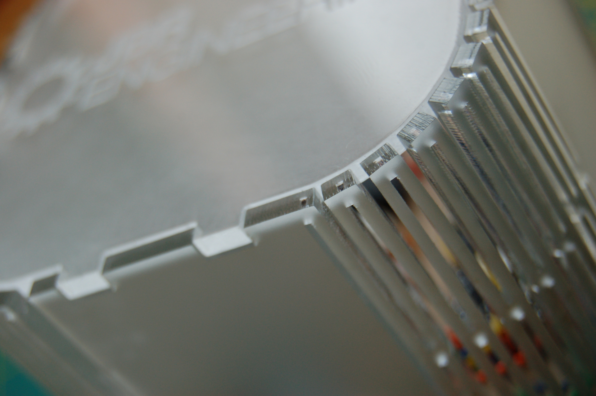
I hadn’t tried kerf bending acrylic until this project. It is stiffer and more brittle than plywood so is much less forgiving, requiring thought into the gap size/link spacing and some trial and error. I’m going to cover what I found and my results in another post.
Result
I’m pleased with the result. I find it quite entertaining to have on my desk and talk to! Playing music is also quite interesting. I’m talking with MACH Acoustics about possible ways to use them in schools as a classroom tool and also a learning tool, with some more refinement of the enclosure and code. We might add a USB connection for example so that students could see the noise levels both visually in colour but also as a waveform. For a classroom it could be tuned to trigger a colour change at a certain noise level.
Here’s a video going over the project and a gallery:


