Wooden Bits – Binary Clock

I’ve been meaning to make a binary wall clock for a while and to also try out kerf bending with the laser cutter. What put me off creating kerf bends before I found OpenSCAD, was the manual creation of all the lines in the right places. It’s the kind of repetitive, uniform task computers were made to do.
Design

Above was what I wanted to create; a square matrix formed from one length of plywood, with the curves creating some organic interest to an otherwise boring shape. I opened Vim and started away in lines of OpenSCAD.
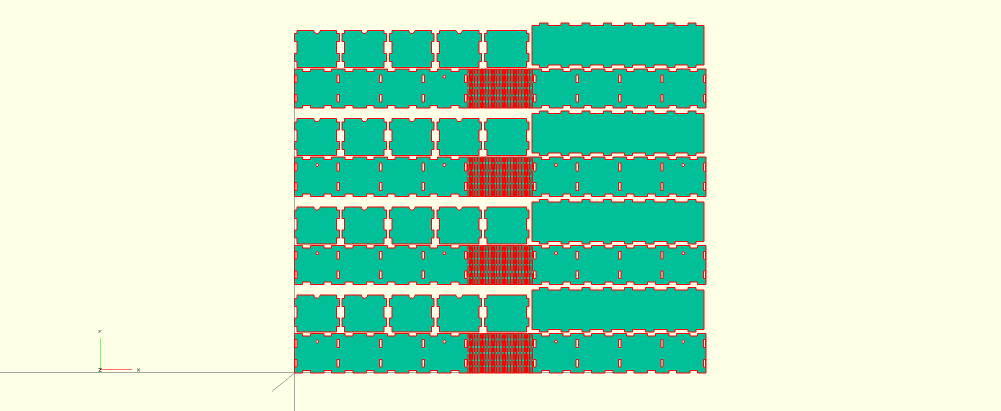
I ended up creating script that could create a one-piece design but would also split the length into divisions. I did this because the length was too big for the cutter bed. For the initial build, each (of four rows) row is separate and then they are all glued together. If I make another I’ll add a dovetail so that each section can be joined, it’s more complicated because you have to alternate the teeth/dents on the middle male components.
Make
There was some tweaking involved of the kerf spacing to get it strong yet bendable but overall it was a relatively pain-free construction.


Electronics
The controller is an Arduino Micro with a DS1307 RTC module and the W2812B LED chain connected to pin 6.
UPDATE I have now created a custom PCB, the size of a single cell.

Code
Features
- Version for Arduino/Attiny328 and Raspberry Pi.
- Scales to any size WS2812 matrix.
- Ability to rotate display.
- Ability to set second indicator pulsing.
- Quarter hour indicator fills n/quarter rows of the display blue (n is the
quarter multiple). - Full rainbow and midday and midnight.
-
setMatrixfor sending any binary size to display; not just time. -
initMatrixMapfor creating lookup map of display.
I had a quick Google for Arduino binary clock code and the top hits weren’t all the elegant. They employed a brute force method of creating if/else for each digit possibility and resulting GPIO set. Due to this they couldn’t scale beyond their original project.
My method is to create an 4 element array of binary nibbles, one for each clock digit. 13:40 would look like this:
{0}{1}{2}{3}
[0][0][0][0]
[0][0][1][0]
[0][1][0][0]
[1][1][0][0]
One can then loop through each binary nyble and use a bit-shift on each bit to set the pixel on or off (there are twice as many for to allow the clock to scale and fill any size matrix):
uint8_t x; // row inc.
  uint8_t y; // height inc.
  uint8_t i; // binary set matrix
  uint8_t yy; // full column inc.
  uint8_t xx = 0; // full row inc.

  for ( i = 0; i < size; i++) {
    for (yy = 0;yy < PIXEL_COLUMN; yy += height) {
      for (y = 0; y < height; y++) {
        for (x = 0; x < {
          if (x == 0 && y == 0) {
            setPixel(pixelMap[xx+x][yy+y],((bMatrix[i] >> yy/height) & 1),color1);
          } else {
            setPixel(pixelMap[xx+x][yy+y],((bMatrix[i] >> yy/height) & 1),color2);
          }
        }
      }
    }
    xx +=
Wiring an LED matrix creates a snakes and ladders index, which is hard to reference without a map. The pixelMap is created like so:
uint8_t i; // row inc.
  uint8_t j; // column inc.
  uint16_t pixel_inc; // pixel number inc.

  /* What we're trying to draw (64 pixel unicorn hat grid) */
  /* It's a snakes and ladders type arrangement for any matrix */
  /*   {7 ,6 ,5 ,4 ,3 ,2 ,1 ,0 },*/
  /*   {8 ,9 ,10,11,12,13,14,15},*/
  /*   {23,22,21,20,19,18,17,16},*/
  /*   {24,25,26,27,28,29,30,31},*/
  /*   {39,38,37,36,35,34,33,32},*/
  /*   {40,41,42,43,44,45,46,47},*/
  /*   {55,54,53,52,51,50,49,48},*/
  /*   {56,57,58,59,60,61,62,63}*/
  /* */

  // The cord either starts at 0 or length of row depending on whether it's rotated
  pixel_inc = rotate ? PIXEL_ROW : 0;

  for (i = 0; i < PIXEL_COLUMN; i++) {
    for (j = 0; j < PIXEL_ROW; j++) {
      // We either increment or decrement depending on column due to snakes and ladders arrangement
      if (rotate) {
        pixelMap[i][j] = (i % 2 == 0) ? --pixel_inc : ++pixel_inc;
      } else {
        pixelMap[j][i] = (i % 2 != 0) ? pixel_inc-- : pixel_inc++;
      }
    }
    pixel_inc += PIXEL_ROW;
    (i % 2 == 0) ? pixel_inc-- : pixel_inc++;
  }
The binary nybles are created using bit-wise comparison on the decimal digit. For the power of ten times, one has to do a extract each digit using a mix of flooring and division/multiplication:
// convert the time into 4 nybles for each column of matrix
  if (hour >= 0 && hour < 10) { bTime[1] = hour | 0b0000; bTime[0] = 0b0000; // 2nd digit still needs clearing } else { bTime[1] = (uint8_t) (hour-(floor(hour/10)*10)) | 0b0000; bTime[0] = (uint8_t) (floor(hour-(hour-floor(hour)))/10) | 0b0000; } if (minute >= 0 && minute < 10) {
    bTime[3] = minute | 0b0000;
    bTime[2] = 0b0000; // 2nd digit still needs clearing
  } else {
    bTime[3] = (uint8_t) (minute-(floor(minute/10)*10)) | 0b0000;
    bTime[2] = (uint8_t) (floor(minute-(minute-floor(minute)))/10) | 0b0000;
  }
The code is on GitHub: https://github.com/tuna-f1sh/wooden-bits
Raspberry Pi
After I’d completed it I felt like porting it to the Raspberry Pi and Pimoroni’s Unicorn Hat. I was already using the Arduino Make Makefile so had a header with declarations unlike most Arduino projects. The main changes were the GPIO functions to actually set the matrix. Thankfully a WS2812 Driver exists with the same functions as the NeoPixel library, so the task wasn’t all the difficult. Rather than referencing the pixels object, the functions are directly called since it’s straight C.
Because the Unicorn Hat is an 8×8 (twice the size of mine), it allowed me to ensure the code scaled to any size matrix and the process created improvements that I carried back to the Arduino code.
Result
I’m pleased with the result. The clock is stable and has so far been running for days without issue. It’s a Christmas present for the lab but my parents want one too so I’ll make another. The next one will be one piece with dovetail joints between sections amongst other points I’d like to improve on:
- Clock set routine invoked from tactile switch or even better a hand wave across one of the cells (the one with the controller in).
- Alarm routine that can be remotely set via phone app – I’d use a bluetooth module for this.
UPDATE: I’ve added both!
Click if you like what you see and want to buy one.


